- {{sigdata.established}} 1977
- {{sigdata.tel}} +86(760)-8521 3999
Cautions and Warnings
Scope of 3L products:
3L components are manufactured and promoted for use in general electronics devices such as audio-video equipment,home electric appliance, office automation equipment,in-car equipment,communication equipment, measurement hardware,machine accessory and medical equipment.
In case of using the product for the purpose other than general electronics devices, please make sure to consult with our business headquarters, branch or business office. When the suggested recommendations are not heeded,3L Group shall not be held liable for any malfunction in or damage to the equipment with which the product is used.
In the event a problem occurs which may affect industrial property and any other rights of 3L Group (or a third party) during the use of the product and information described in this catalog, 3L Group shall not be held liable for any such problem, nor grant any license to the offending party.
Please pay attention to the storage conditions [ Temperature: below 35℃, humidity: 35-65% RH ]. If the products listed herein are stored over 1 year, the solderability of their terminals may be deteriorated.
General stipulations for coil use:
- a. The specification is subject to change without prior notice as it deems necessary to reflect improvements or changes.
- b. Please note the arrangement of the non-magnetic shield type coil when you design the printed circuit board. Magnetic interference may cause malfunction.
- c. Products should not be kept in unsuitable storage conditions, such as areas susceptible to high temperatures, high humidity, dust or corrosion.
- d. The soldering conditions should also be observed. Temperatures quoted in relation to wave soldering refer to the pin, not the housing.
- e. Please do the thermal design of the set in consideration of coil self-heat, because the coil generates heat when electric current is applied.
- f. Don't use products in a place where dew condenses. Please pay special attention when using products in a sealed condition since dew condensation will be caused by temperature change.
- g. Always handle products with care.
- h. Don't touch electrodes directly with bare hands as oil secretions may inhibit soldering. Always ensure optimum conditions for soldering.
- i. Don't bend the terminals or subject them to excessive stress.
- j. Please ensure that all terminals and case lugs are completely fixed with solder onto PCB. Avoid placing coils near the edge of the PCB.
- k. Ensure the tuning slug or cap is not fixed by solder flux during the production process.
- l. Refrain from rinsing coils. If necessary, please consult with our company.
- m. Our SMD coils are designed for automatic mounting. Please be careful if soldering by hand. Don't touch any exposed winding part and avoid coming into contact with the guide of electrode in automatic mounting.
- n. Our specification limits the quality of the component as a single unit. Please ensure the component is thoroughly evaluated in your application circuit.
- o. When using our high voltage inverter transformers, place 2mm away from the electric conductor.
- p. The following points must be observed if the components are potted in customer applications:
---Many potting materials shrink as they harden. They therefore exert a pressure on the plastic housing or core. This pressure can have a deleterious effect on electrical properties, and in extreme cases can damage the core or plastic housing mechanically.
---It is necessary to check whether the potting material used attacks or destroys the wire insulation, plastics or glue.
---The effect of the potting material can change the high-frequecy behaviour of the components.
---Ferrites are sensitive to direct impact. This can cause the core material to flake, or lead to breakage of the core.
---For molded product, if this product is left in a humid environment for a long period of time, rust may appear on the surface. However, this does not affect performance.
---Even for customer-specific products, conclusive validation of the component in the circuit can only be carried out by the customer.
Important Notes
The following applies to all parts named in this publication:
1. The warnings, cautions and product-specific notes must be observed.
2. In order to satisfy certain technical requirements, some of the products described in this publication may contain substances subject to restrictions in certain jurisdictions(e.g. because they are classed as hazardous).Useful information on this is available on our Material Data Sheets from Quality Assurance Department or sales Department. Should you have any more detailed questions, please contact our Sales offices.
3. We constantly strive to improve our products. Consequently, the products described in this publication may change from time to time. The same is true for the corresponding products specifications. Please check therefore to what extent product descriptions and specifications contained in this publication are still applicable before or when you place an order.
4. We also reserve the right to discontinue production and delivery of products. Consequently, we can not guarantee that all products named in this publication will always be available.
5. Some parts of this publication contain statements about the suitability of our products for certain areas of application. These statements are based on our knowledge of typical requirements that are often placed on our products in the areas of application concerned. We nevertheless expressly point out that such statements cannot be regarded as binding statements about the suitability of our products for a particular customer application.
6. As a rule, 3L is either unfamiliar with individual customer applications or less familiar with them than the customers themselves.For these reasons, it is always ultimately incumbent on the customer to check and decide whether a 3L product with the properties described in the product specification is suitable for use in a particular customer application.
7. We also point out that in individual cases, a malfunction of electronic components or failure before the end of their usual service life cannot be completely ruled out in the current state of the art, even if they are operated as specified.
8. The aforementioned does not apply in the case of individual agreements and the foregoing customer-specific products.
Notes for Electrical Characteristics Test
Note 1. Temperature: 25 +/- 5℃ (room temperature), humidity: 35-65% RH, this applies to all the products unless specifically specified.
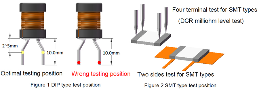
Note 2. For DIP type products, when the pin length is more than 5mm, the test position should be at 2-5mm away from the bottom of the product; For SMT type products, ensure better contact between the products and the tooling, as shown below:
1. Inductance Test
There could be measurement deviations with different instruments due to different test principles / internal resistance. Open and Short compensation is performed before testing. Select the measurement fixture or testing wire that goes with the original instrument.
2. Leakage Inductance Test
There could be measurement deviations with different instruments due to different test principles / internal resistance. Open and Short compensation is performed before testing. Select the measurement fixture or testing wire that goes with the original instrument.
3. DCR Test
Shorten the testing wire as much as possible to ensure better contact between the products and the tooling; there can be deviations for the DCR if the testing tooling contact surface is worn out or if the testing method is not correct, especially for low DCR products.
4. Rated Current,Saturation Current,Temperature Rise Current
The saturation current is according to the initial inductance drop amount; the rated current is generally taken by the smaller value between the saturation current and temperature rise current.
5. Q Factor / SRF / Z Test
Shorten the pin length as much as possible to ensure better contact between the products and the tooling; there can be deviation if the testing tooling contact surface is worn out or if the testing method is not correct.
6. Turns Ratio and Phase Test
There can be deviations for turn counts ratio when there is magnetic leakage or air gap in the core center, please pay attention to the differences during testing. If the air gap is too large, planar cores can be used for confirmation, be careful to choose the foot position when testing the polarity.
7. Hi-Pot Test
Choose AC or DC accordingly during Hi-pot testing since they are different. If the humidity is too high or there is pollution on the surface,the Hi-pot test might fail. Please avoid testing at high humidity condition and keep the tooling and products clean. The Hi-pot test is destructive test and repeat testing should be avoided.
8. IW T Test
Carefully choose the voltage and standard sample for the testing, IWT test is destructive testing and repeat testing should be avoided. If you have any questions, please contact us.